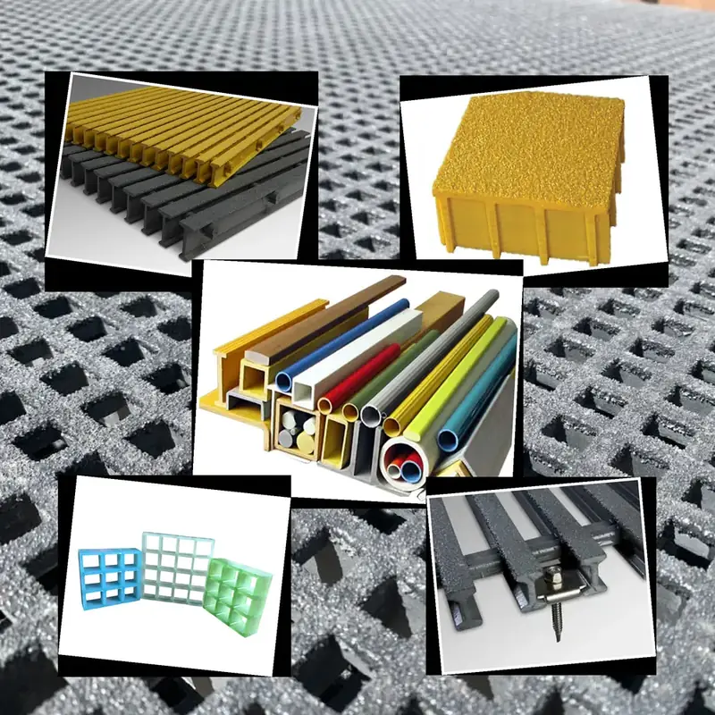
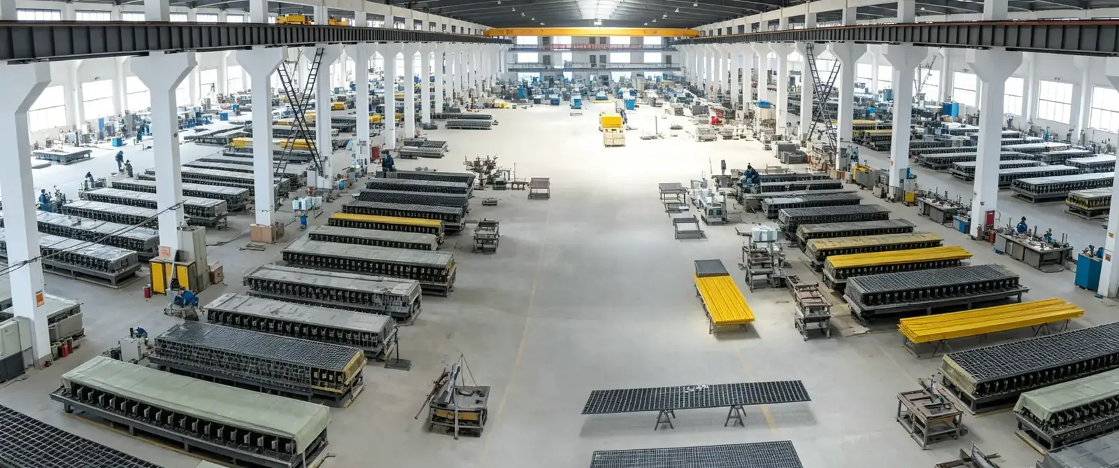
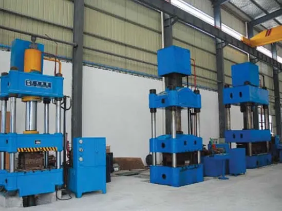
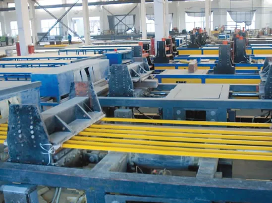
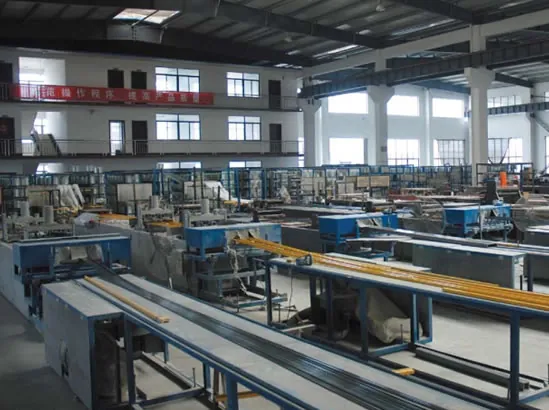
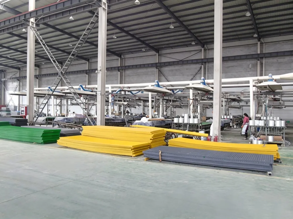
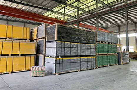
Pultruded FRP grating is engineered with continuous glass reinforcement for high load and long span; design follows ASTM load tables for bar height and bearing spacing.
- Best for: engineering-grade high-load grating
- Choose pultruded for: spans/loads beyond molded capacity
- Key spec: ASTM load table, ISO 9001, 25–100 mm bars
1. Pultrusion Manufacturing Technology
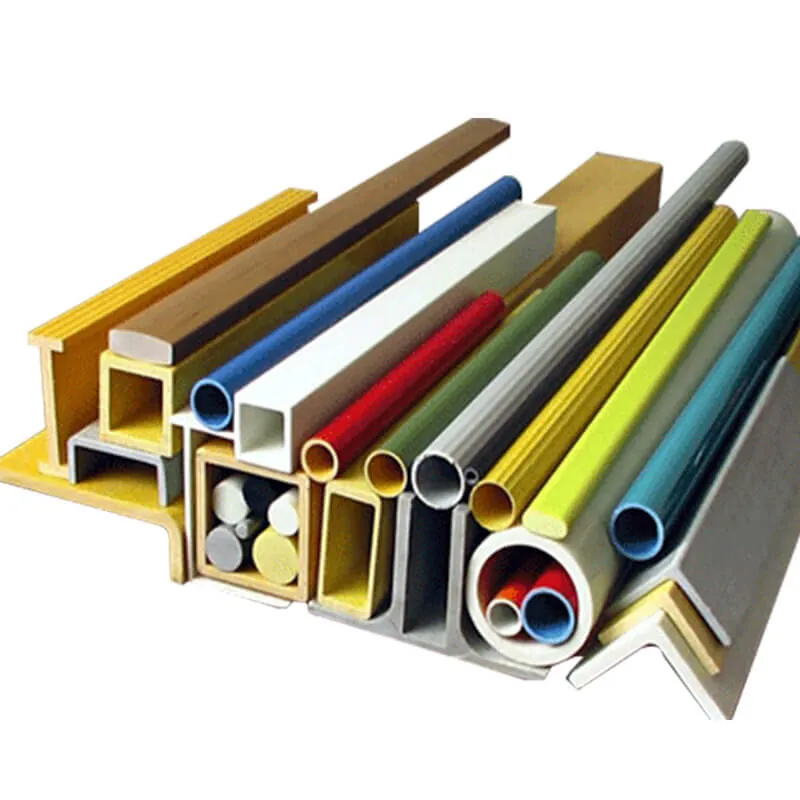
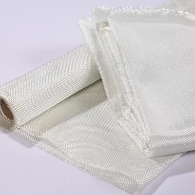
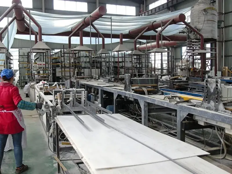
Pultruded grating is manufactured by pulling continuous glass fiber rovings through a resin impregnation bath, then through a precision-heated steel die that cures the resin into a constant cross-section profile. The process produces bars with highly aligned unidirectional fibers (70-75% fiber content by weight), resulting in exceptional longitudinal strength. Typical pultrusion speed: 0.5-2.0 m/min, die temperature: 150-180°C with multi-zone control.
2. Cross-Section Design & Profiles
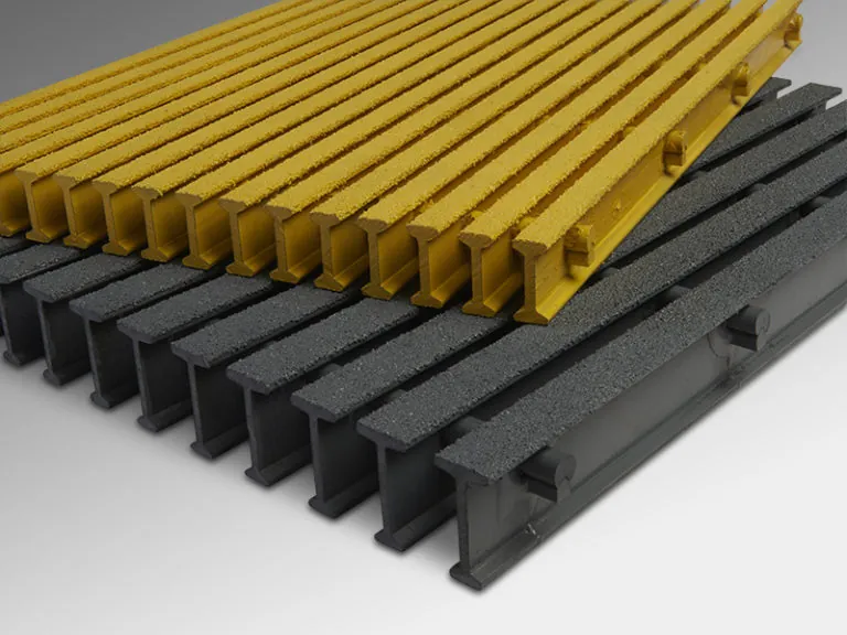
Common pultruded grating bar profiles include: I-beam (standard for most applications), T-bar (for increased top surface area), rectangular tube (for high torsional stiffness), and custom profiles. Bar heights range from 25mm to 100mm, with wall thickness from 3mm to 8mm. Bearing bar spacing is typically 30mm, 38mm, or 50mm on center. Cross bars are typically 6mm diameter solid rods or 25×3mm flat bars, spaced at 100-150mm intervals.
3. Load Capacity & Structural Calculation
50mm deep I-bar pultruded grating at 1000mm span achieves: allowable uniform load 25 kN/m², point load capacity 5 kN at center, maximum deflection L/240. Bending strength: 350-420 MPa, elastic modulus: 20-25 GPa (longitudinal). Design calculations follow ASTM D3916 (pultruded shapes) and EUROCOMP design code. Safety factors: 2.5 for ultimate strength, 1.5 for serviceability (deflection).
4. Connection & Assembly Systems
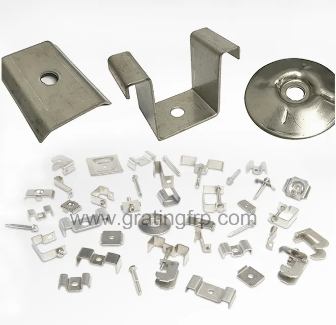
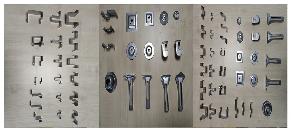
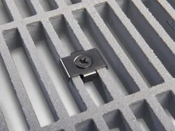
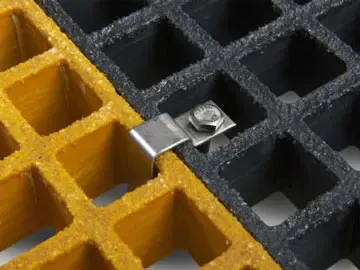
Pultruded grating panels are assembled using: stainless steel clips (M-clip, C-clip, G-clip types), FRP bolted connections, and adhesive bonding. Clip systems allow for easy installation and removal. Recommended fastener spacing: 600mm maximum for bearing bars, 300mm for edge supports. Thermal expansion coefficient: 12-15 × 10⁻⁶ /°C (longitudinal), requiring expansion gaps of 3-5mm per panel at installation.
5. Heavy-Duty Application Trends 2026
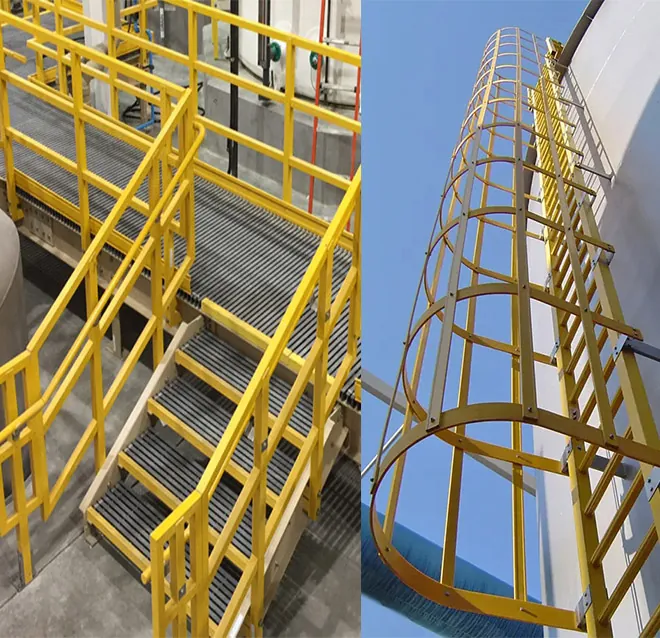
Emerging heavy-duty applications for pultruded grating include: mining industry walkways and conveyor platforms (replacing steel in corrosive mine environments), offshore oil & gas platform decking (fire-retardant vinyl ester systems), heavy industrial flooring for forklift traffic (65mm deep I-bar rated for 3-ton forklift), bridge decking and pedestrian bridges (lightweight, corrosion-free), and renewable energy access platforms (wind turbine interiors, solar farm maintenance walkways). The heavy-duty pultruded grating segment is growing at 8.5% CAGR, outpacing the overall FRP grating market.
Deflection, Vibration Comfort and the L/200 Criterion
Pultruded grating carries load primarily along the pultruded chord, which is why its numbers look strong on a data sheet and feel slightly livelier underfoot than a molded panel of the same depth. The engineering answer to that liveliness is not to chase a higher strength figure but to design to a deflection limit. The L/200 simply-supported criterion keeps the panel stiff enough for operator comfort and trolley wheels, and it is the number that should drive the span choice, not the ultimate load.
As a reference, pultruded sections graded to L/200 at simply-supported spans carry roughly 35 kilonewtons per square metre at a 600 millimetre span for the 38 millimetre T-bar, rising to 48 at the 50 millimetre section and 62 at the 65 millimetre heavy section. Those values drop as span grows, which is exactly why walkway design is a span game: moving a support beam 300 millimetres closer often solves a comfort complaint without changing the grating depth.
- Design to the L/200 deflection limit, not to the ultimate strength figure.
- Shorter spans buy comfort cheaper than deeper sections.
- Use the supplier load table at the actual 600, 900 or 1200 millimetre span.
Indicative L/200 load values by section and span, pultruded with molded reference
| Section | 600 mm span | 900 mm span | 1200 mm span |
|---|---|---|---|
| Pultruded 38 mm T-bar | 35 kN/m² | 18 kN/m² | 9 kN/m² |
| Pultruded 50 mm T-bar | 48 kN/m² | 26 kN/m² | 14 kN/m² |
| Pultruded 65 mm heavy | 62 kN/m² | 35 kN/m² | 20 kN/m² |
| Molded 38 mm, reference | 25 kN/m² | 12 kN/m² | 6.5 kN/m² |
Pultruded versus Molded Grating: When to Choose Which
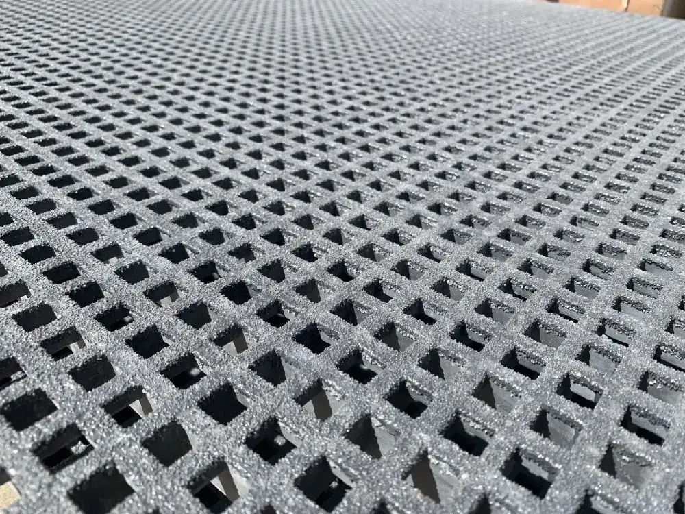
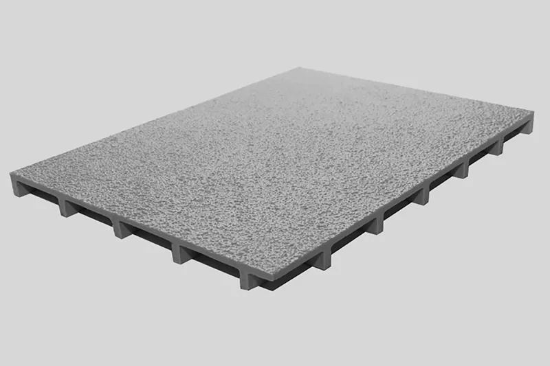
Pultruded and molded grating are not two versions of the same product; they are two structural philosophies. Pultruded bars carry load along one axis, which makes them the right choice for long spans, trolley lanes and heavy equipment platforms where the design direction is known. Molded grating distributes load in both directions, which makes it the right choice for floor areas with irregular foot traffic, random rolling loads and frequent cutouts around equipment.
The decision usually comes down to three questions. Is the load direction known? Go pultruded. Is the layout irregular with many notches? Go molded, because a pultruded bar cut across its axis loses its advantage at the cut. Is the duty chemical more than structural? Molded often wins, because the molded grid has more resin-rich surface and no unidirectional roving ends exposed at a cut. When in doubt, ask the supplier to compare the two on the actual plan rather than choosing by thickness alone.
- Known load direction and long spans: pultruded.
- Irregular layout with many notches: molded.
- Chemical duty over structural duty: molded often has the edge.
Pultruded versus molded at a glance
| Criterion | Pultruded | Molded |
|---|---|---|
| Load direction | Strong along the chord | Biaxial distribution |
| Best span | Longer, known direction | Shorter, irregular |
| Cutouts | Loses advantage across the cut | Cuts well in both directions |
| Chemical surface | Roving ends exposed at cuts | Resin-rich surface all around |
Frequently Asked Questions
FRP (Fiberglass Reinforced Plastic) grating is a molded or pultruded fiberglass composite grid used for corrosion-resistant walkways, platforms and floorings. It combines glass fiber reinforcement with thermoset resin (polyester, vinyl ester, epoxy) for superior strength-to-weight ratio, zero rust and 20+ year service life.
Because it carries load along the pultruded chord, which is stiff on axis but slightly livelier across it. The fix is not a stronger section but a shorter span. Design to the L/200 deflection criterion rather than the ultimate strength figure; moving a support beam closer usually solves the comfort complaint without changing the grating depth.
Choose pultruded when the load direction is known and spans are long, such as trolley lanes and equipment platforms. Choose molded when the layout is irregular, with many notches around equipment, or when the duty is more chemical than structural, because molded grid has a resin-rich surface and distributes load in both directions.
As an L/200 simply-supported reference, the 50 millimetre pultruded section is graded around 48 kilonewtons per square metre at a 600 millimetre span, 26 at 900 millimetres and 14 at 1200 millimetres. Use the supplier table at the actual span on the project, because values fall quickly as span grows, and confirm the number against the final layout.
You can, but you lose the advantage at the cut, because the bar is strong along the chord and not across it. Where the layout has many notches, molded grating usually performs better, because its biaxial grid keeps carrying load in both directions after a cut. If a pultruded bar must be cut, seal the exposed roving end and check the span around the cut.
Molded often has the edge, because the molded grid has a resin-rich surface on all sides and exposes no unidirectional roving ends at a cut. Pultruded works too, but the cut ends need sealing and the resin grade must be matched to the chemical. Tell the supplier the actual exposure rather than choosing by product family alone.